Product 8.3
 A tool for the optimization and control of coupled networks for the integration of the electrical grid, polygeneration systems and electric vehicles
The tool developed is an energy management system for general polygeneration system, like sustainable districts (Figure 1), to provide the optimal scheduling of production plants, storage systems, electric vehicles and other components in order to minimize costs. The tool includes different electrical models to represent a general low voltage grid, coupled with thermal models for the heating and cooling systems, due to the presence of cogeneration microturbines and heat pumps.
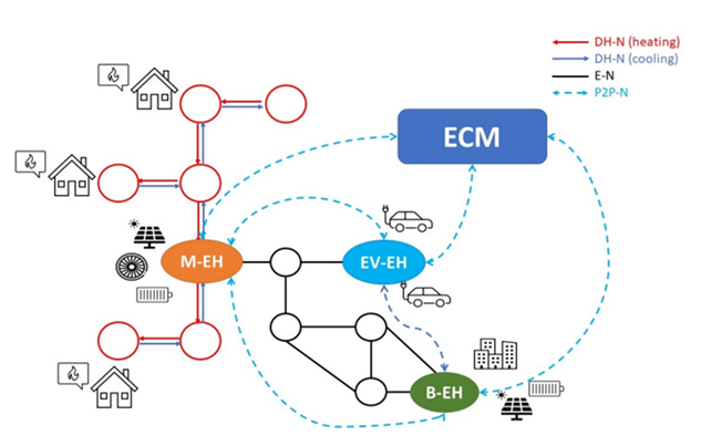
Figure 1. Polygeneration system
The tool includes appropriate models for charging stations and electrical vehicles and the thermal models for district heating and buildings.
Uncertainties are faced by a model predictive approach. The tool can be used both for districts owned by a single agent (like microgrids, campuses) and/or by multiple agents representing buildings, different microgrids, or shared resources (like storage or PV). The tool was developed using as a use case and reference the Savona Campus.
The optimization problem
To achieve the optimal operation for a plygeneration system, a multi-objective problem was formulated. In fact, even if the operational costs are the most important factor in the majority of the energy management problems, since the thermal part is considered, the comfort of the people in the buildings must be carefully considered. Thus, the goal of the control algorithm is to minimize the operating cost of the infrastructure, while, at the same time, maintaining comfortable operating conditions inside the buildings. In order to do this, the temperature of each building must be kept within a specific range during certain time intervals along the day More specifically, the objective function is composed of three main terms:
- Thermal comfort
- Grid cost
- Fuel cost
The first one reflects the requirement that the temperatures in the building rooms must fit within a range, the second one is relevant to the total energy purchased and sold to the national grid by the polygeneration system, and the third one is relevant to the gas consumption for boilers and cogenerators.
Distributed architecture for building temperature control
A distributed architecture for building temperature control was developed for the project. In a distributed architecture , nodes communicate only with their neighbours, local controllers (Figure 2). Generally, this architecture is used for applications in which there is a physical network or when different agents should operate in a coordinated manner. Advantages of a distributed architecture include: low computation effort for large networks, parallel computation, privacy, resiliency to attacks and no commercial tools needed to solve optimization problems in each node.
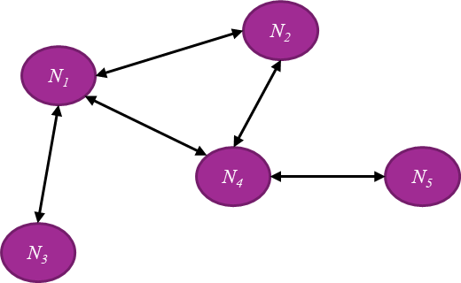
Figure 2. Distributed architecture
Real-time simulations to test the models and detailed building models
The use of a real-time simulator has been explored during the development of the product. A real-time simulator emulates a device or system (e.g., PV inverter, distribution grid) in real time; interfaced with a real control and management system, it allows to test its performance and fine-tune its parameters, in different operating conditions, before the actual installation in the field. Examples of applications include:
- simulation of storage systems connected to the distribution network, for the development of control and management algorithms
- simulation of buildings equipped with geothermal heat pumps, to develop demand response techniques
Furthermore, a workflow was identified to develop a detailed building model from available data, such as design documents, both architectonic and related to the HVAC equipment sizing.
Pilot
The tool has been tested on data from the Savona Campus of the University of Genoa, which houses an array of facilities, including classroom buildings, laboratories and SME offices. The Savona Campus also hosts the Smart Polygeneration Microgrid (SPM, Figure 3), characterized by photovoltaic plants (PV), cogeneration microturbines coupled with absorption chillers, an electrical storage system, boilers, and heat pumps.
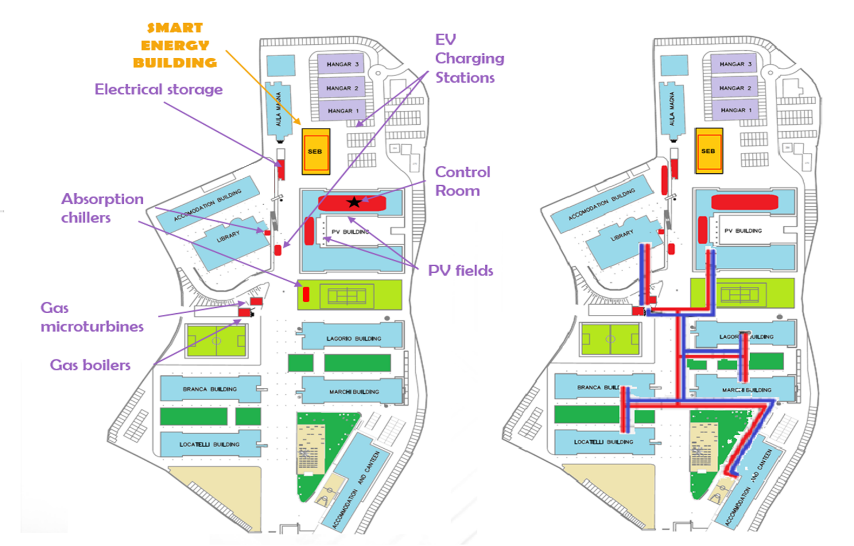
Figure 3. Schematic representation of the electric and the thermal plants/networks
A Smart Energy Building (SEB, Figure 4), equipped with PV, thermal solar collectors, and a geothermal heat pump, is connected to the microgrid. Thermal (heating and cooling) and electrical loads are present too.
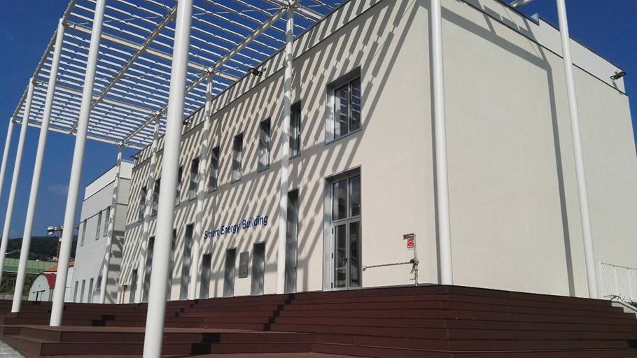
Figure 4. Smart Energy Building
Results
The following Figure 5 shows an example of optimal scheduling (electrical balance) for the next day, for a winter day.
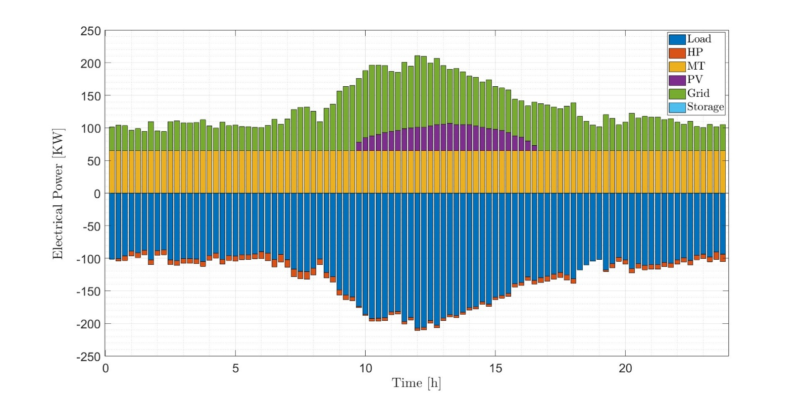
Figure 5. Electrical optimal scheduling
In Figure 6, in the context of the Building temperature dynamics modelling and control, the comparison of the proposed decentralized algorithm with a traditional approach, based on thermostats, is presented.
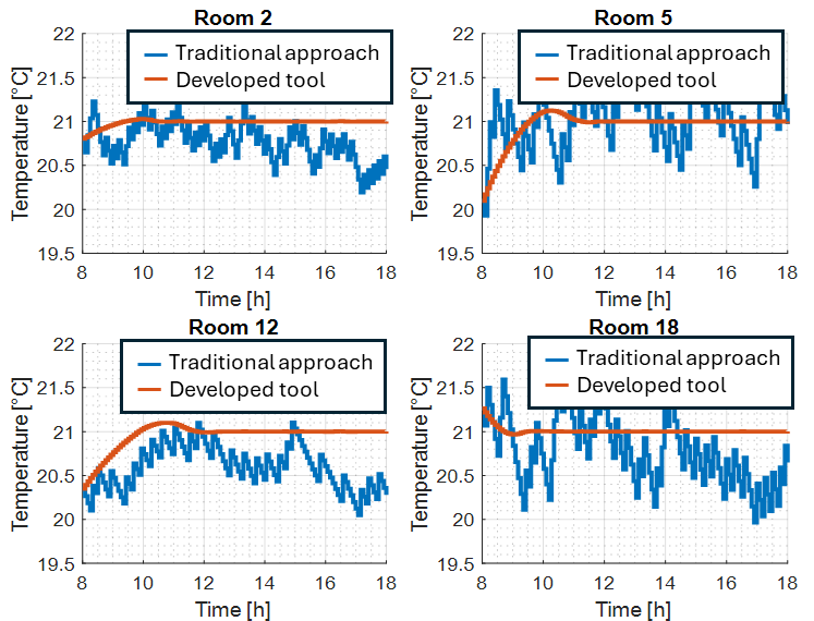
Figure 6. Building temperature control: comparison with a traditional approach
Finally, in Figure 7, results from the simulation of a demand control action (SEB geothermal heat pump turned off and air handling unit turned off) are illustrated: the temperatures remain in acceptable limits during the action.
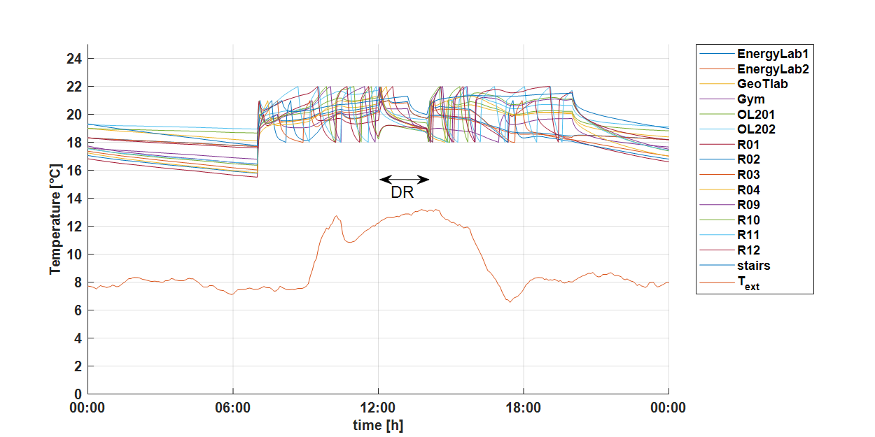
Figure 7. Building temperature control: simulation of a demand response action